USB-C Power Metering with the ChargerLAB KM003C: A Google Twinkie Alternative?
by Ganesh T S on July 5, 2023 8:00 AM EST- Posted in
- Gadgets
- USB PD
- Power Assessment Tool
- USB-C
Hardware Design and Software Interface
The internal layout of all USB-PD sniffers is quite similar. A microcontroller acts as the control center (interfacing with the data monitoring host and tapping into the CC lines). Power monitoring ADCs (TI INA family in most cases) are placed on the VBUS and VCONN lines after placing a shunt resistor in the path. These INA chips interface with the microcontroller over an I2C bus. The schematic for the Twonkie 2.0 (a Twinkie clone with updated components that is easier to prepare for DIY folks) is reproduced below.
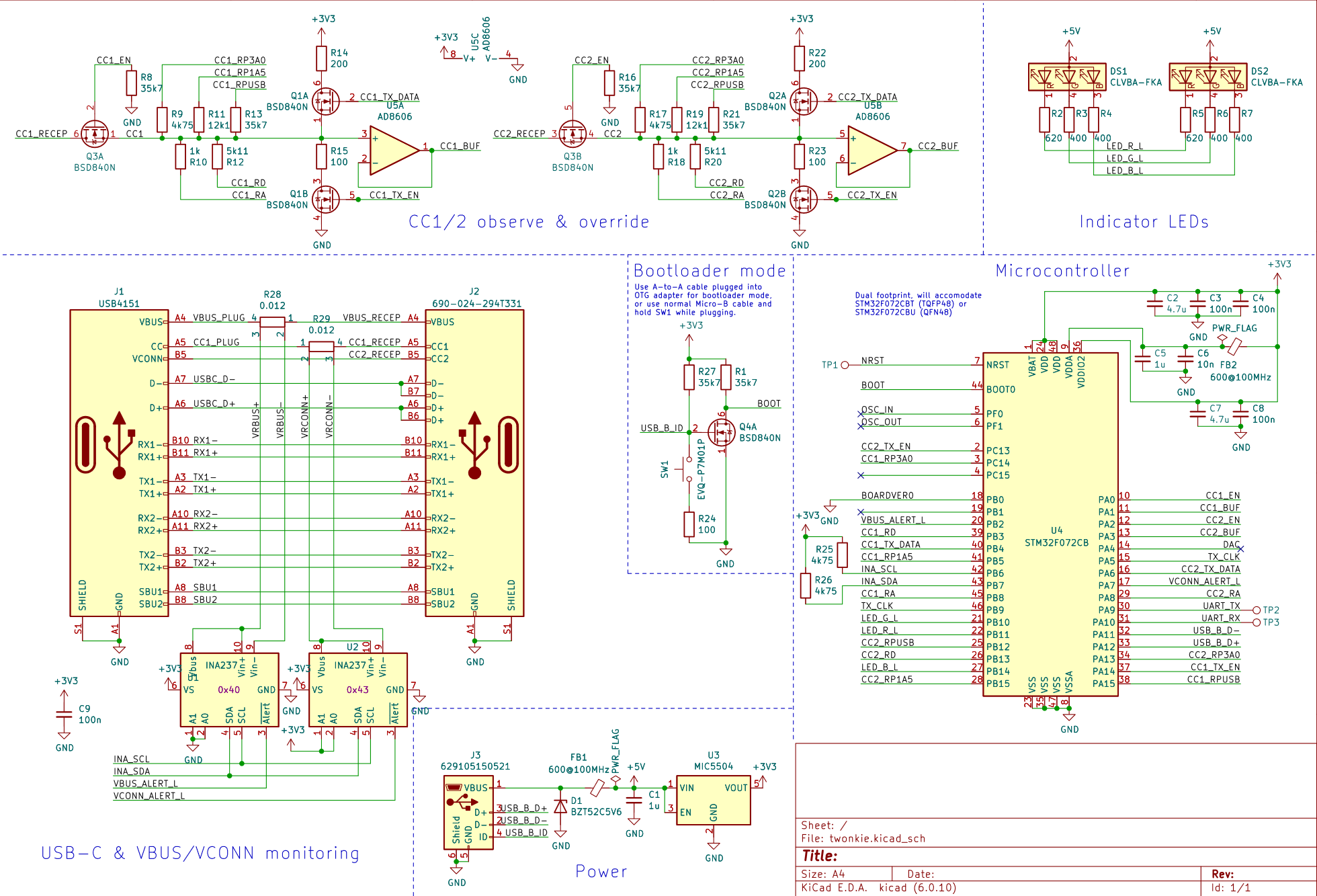
Twonkie 2.0 Schematic - STM32F072 + 2x INA237 + 2x 12 mOhm Shunt Resistors
The Google Twinkie / USBC-TKEY differs only slightly from the above schematic, with 2x INA231 power monitoring ADCs in place of the 2x INA237. There are multiple resistors in the CC observation path, and these enable the placement and removal of the Rp / Ra / Rd from the Twinkie's CLI. The STM32F072 microcontroller has a Cortex-M0 CPU running at 48 MHz, 128KB of flash memory, and a 16KB SRAM.
The ChargerLAB KM003C's structure is likely to be similar to the above. Based on the photograph of the KM002C's PCB (the KM003C is an updated version with a larger screen, gravity sensor, and a supercapacitor), the main differences appear to be the use of a Huada HDSC HC32F460 microcontroller, multiple INA228 ADCs, and 20 mOhm shunt resistors.
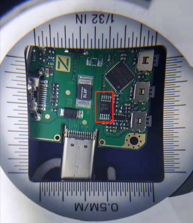
KM002C PCB, with the TI INA228 ADC boxed in red
The HC32F460 is a highly advanced microcontroller compared to the STM32F072. It has a Cortex-M4 CPU (with floating point support) running at 200 MHz, 512KB of flash memory, and 192KB of SRAM. This allows the implementation of a fairly complicated user interface with built-in real-time graphing capabilities - features that are not present in the original Twinkie design. We believe that the KM003C includes at least 5 ADCs in order to measure the voltage on both CC lines as well as the D+ and D- lines (in addition to the VBUS). Voltage measurement on the D+ / D- pins is apparently necessary in order to detect and support custom fast-charging protocols, as indicated in the table below from the KM003C's user manual.
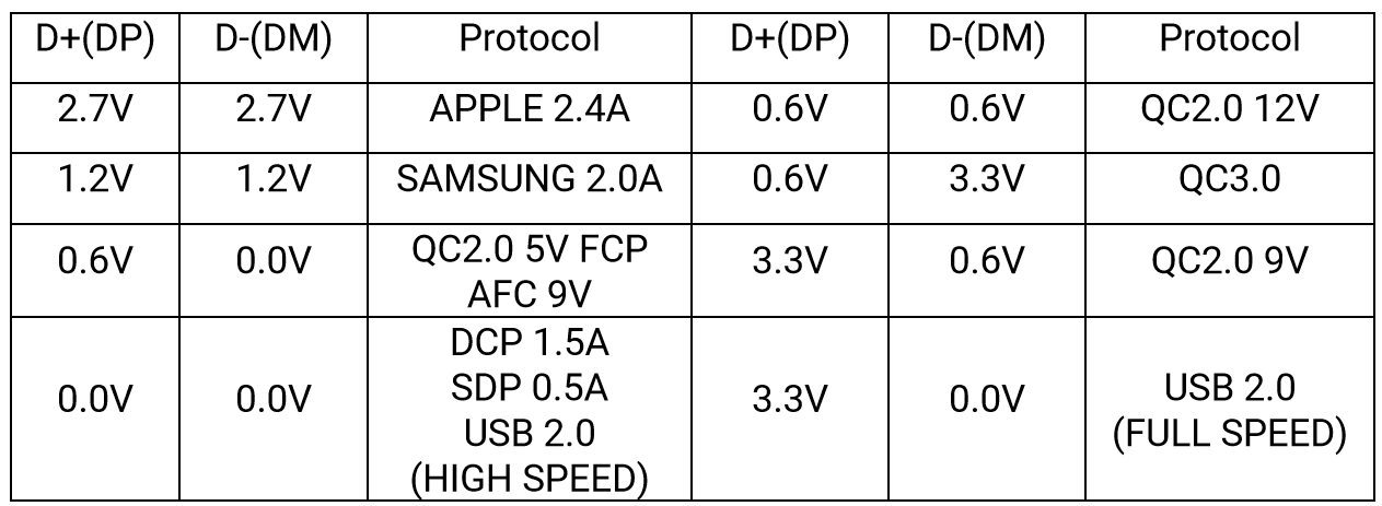
One of the bugs in the KM003C hardware design that has been acknowledged by ChargerLAB is the absence of support for USB 2.0 data passthrough. It is likely that the voltage monitoring on these lines for fast charging protocol detection purposes is breaking the data lines for normal operation. It is an unfortunate side-effect that hopefully gets fixed by ChargerLAB in the next hardware iteration.
On-Device Interface
Moving on to the external hardware aspects, the KM003C is equipped with a vibrant 240 x 240 1.54" IPS screen and four physical push buttons. These allow the user to navigate through the various on-screen options for activation of different features, and also include special signals to modify certain settings quickly (such as a long press on the 'Confirm' button to alter the sampling rate when the dashboard screen is active). The gallery below presents the various features available via the device screen.


After power up (and showing an optional startup image set up through the PC software), the screen lights up with the dashboard that provides important information at a glance - the voltage, current, and power consumption inferred from the parameters on the VBUS line, the charging protocol (if applicable), and voltages on the CC and D+/D- lines. The next interface is the application screen from which the charging protocol support detection can be triggered. This involves ensuring stable power supply through the HID port and connecting the Type-C male port to the power supply of interest. The female port should be left unconnected. Under this option in the interface, it is possible to trigger cable simulation (by selecting 'No e-marker'), request for a specific PD type (after selecting 'Auto'), and scan for different charging protocols support. Yet another option under the application screen is 'Modules'. Under this, various value-adds such as USB-C cable e-marker reading, and Apple charger genuineness checking are currently available. ChargerLAB plans to add testing for cable resistance also in the future.
Under the Settings screen, the display brightness and startup screen can be adjusted. Storage management options are also available. Language settings (Chinese or English) and device information, as well as the option to reset all settings to default can all be accessed from the same screen.
The real-time curves interface allows the user to view the voltage / current on the VBUS line, or the voltages on the D+ / D- lines, or the voltages on the CC1 / CC2 lines as a function of time. The screen also helpfully notes the sampling rate on the top left corner. The data storage interface records the charge and energy values from the INA ADC chip for the VBUS line. The save interval is configurable and the starting and stopping of the recording can be triggered based on the current in the line. Up to 40 different data sets of 10000 points each can be stored in the 4MB of memory available in the device.
PC Software Features
ChargerLAB provides a Windows application that can be used to manage multiple USB power testers from a single pane. Our evaluation was with a single KM003C in the list, which is displayed on the left in the interface. The application starts up with a 'Data Recorder' view. The top part of this view has all the parameters present in the on-device screen's dashboard interface, while the bottom part has a real-time chart (with the available parameters on either side of the title). On the right side, a button to trigger the chart updates is available. The sampling rate can also be adjusted. Available rates are 1, 10, 50, and 1000 samples per second. The cache depth on the PC side is also configurable.


The software interface language can be modified from the triangular drop down on the top right near the window controls. However, some options continue to remain in Chinese even after the language is set to English. However, the software is intuitive enough for that to not be too much of a concern. The device firmware, as well as the application itself, can be updated from within the program. The 'PD Analyzer' view shows a real-time view of the various voltages and currents, along with a tabular view of the PD handshake process. Various other options such as saving graphs, recording data to a CSV or SQLite DB on the PC, etc. are available, as shown in the gallery above.
Open APIs
The Windows application is closed-source, but ChargerLAB provides some documentation in their HID Demo archive. The document is in Chinese, but I used Google Translate to get an inkling of the contents. From previous reviews, I have found that links often go stale. In order to avoid that with the KM003C API description, a screenshot of the translated version is provided below.
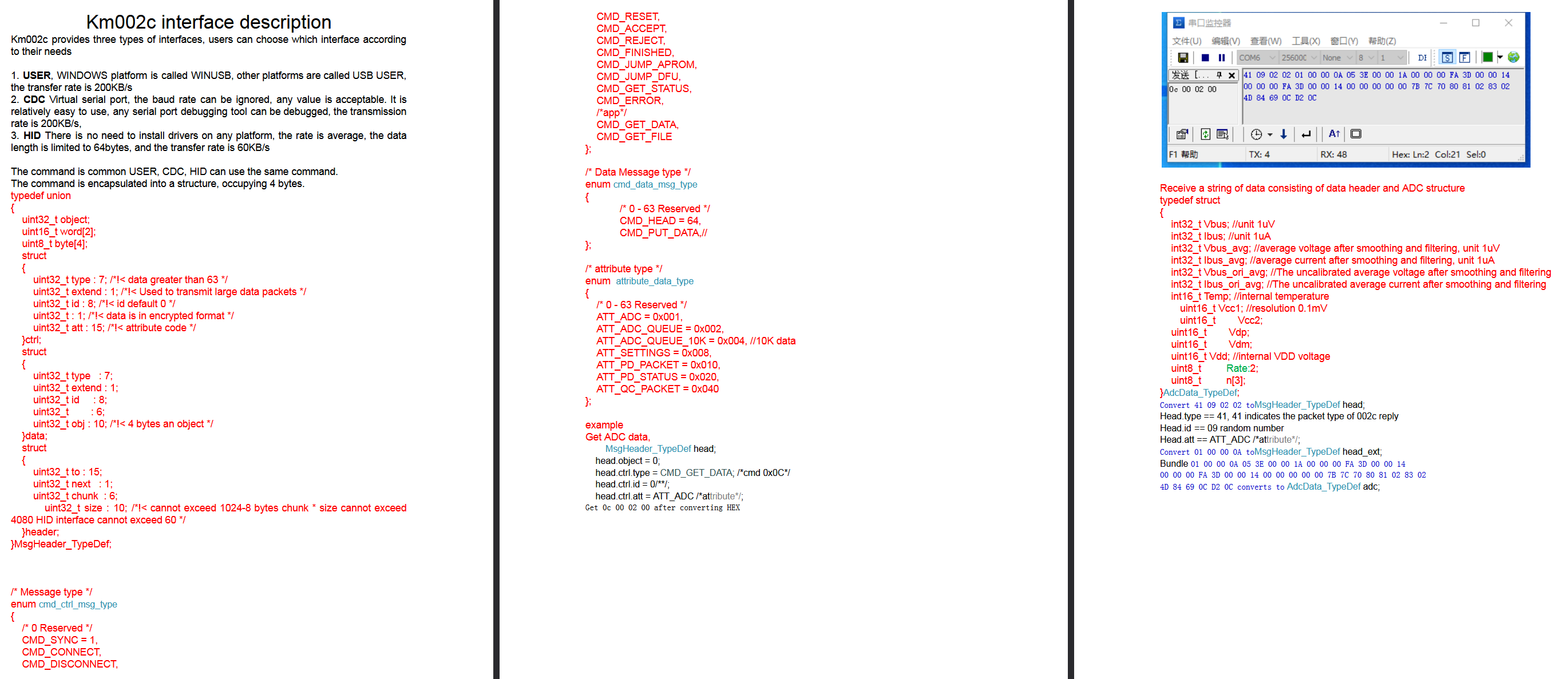
Click for a higher-resolution version of the API document
It is possible that ChargerLAB might update the APIs in the future. In that case, the latest version can be obtained from the FAQ section on their support page. ChargerLAB states there are three interfaces available - as a WinUSB (vendor specific interface) device, a HID device, or a virtual serial port (CDC). The next couple of sections take a look at how these interfaces can be taken advantage of in different operating systems.


20 Comments
View All Comments
ballsystemlord - Wednesday, July 5, 2023 - link
It's unfortunate that the KM003C is windowz only closed source.ganeshts - Wednesday, July 5, 2023 - link
It is not a major problem, as I have demonstrated in a couple of sections. You can use libusb or any other serial port access program to communicate with the KM003C and create a wrapper suited for your particular use-case.That said, one aspect I should have mentioned in the conclusions is related to the ability to update the firmware independent of the closed-source Windows program. Coupled with better API documentation, that would basically make the device pretty functional without having to rely on the closed-source program.
ballsystemlord - Wednesday, July 5, 2023 - link
Oh, I see.QChronoD - Wednesday, July 12, 2023 - link
Since you posted a screenshot of the code for connecting and pulling out the relevant power data, are you OK with people using it? Are you planning on posting it on github or somewhere?ganeshts - Thursday, July 13, 2023 - link
Absolutely! Code is free for anyone to start off with as the base point for their own programs.My github account has been idle for a few years now. I will probably upload a refined version of the code that appears in this review later this year when I get time. The only reason I didn't post the code as text is to avoid making the review appear like a StackOverflow post :)
TrevorH - Thursday, July 6, 2023 - link
You could have saved me from going straight to the last page by putting the price at the top of the article. At $10 I would have snapped your hand off, at $110 it's a definite no.ganeshts - Thursday, July 6, 2023 - link
I think it would be impossible to hit $10 for this type of product. Even BOM cost for microcontroller + 5 ADCs would easily exceed that (even if they are bought in 1Ku quantities). Need to add software development and distribution costs. I would imagine break-even is itself around $40 - $50.ads295 - Saturday, July 8, 2023 - link
+1It's not for "hobbyists" as mentioned in the article.
Bp_968 - Thursday, August 3, 2023 - link
Not sure I agree that 50$ puts it out of reach of "hobbyists". I'm a hobbyist and own a oscilloscope, and a number of other test tools more expensive then 50-100$. If all your doing is seeing what voltage your usb battery is negotiating with your switch or steamdeck then yes, this device is overkill. But if you building anything that's using PD or other usb-c features this could be extremely useful.I'm unlikely to build anything anytime soon that would require the features this thing supports but I still want one! ;)
DanNeely - Thursday, July 6, 2023 - link
"The KM003C can support up to 50V / 6A (full USB-PD 3.1 specifications, with EPR up to 240W)."Unless this device is going significantly beyond USB-PD levels I believe this should read 5A not 6.